Here is what you will need:
- Xbee radio
- Xbee breakout board
- Arduino microcontroller board with USB connection
- USB A-to-B type cable
We will use Arduino microcontroller board as USB-to-TTL converter.
Circuit

Please refer to Xbee - Part 6 - Pin configuration - linux - Freemindscafe for details about Xbee pins configuration
Connections
- Make sure arduino is unplugged from USB or from any other external power supply
- Carefully remove the ATMEGA chip ( The other option is to connect RESET pin to GND)
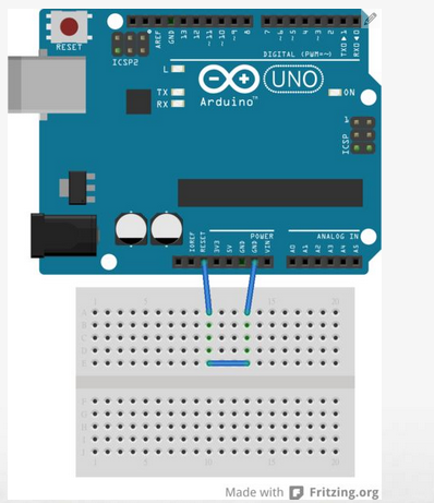
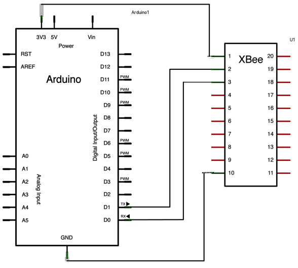
- Connect a wire from 3.3 V socket to XBee’s pin 1
- Connect a wire from GND to XBee’s pin 10
- Connect the TX pin (pin 1) on arduino to XBee’s pin 2 (Tx/Dout)
- Connect the Rx pin (pin 0) on arduino to XBee’s pin 3 (Rx/Din)

- You must be using some XBee breakout board. Please refer to your breakout board’s schematic to connect to the right XBee pins.
- Breakout board must have voltage level shifter so that 5V signals can be supplied to Xbee without any damage to it. Then 5V pin of Arduino can be connected to 5V input of the breakout board.
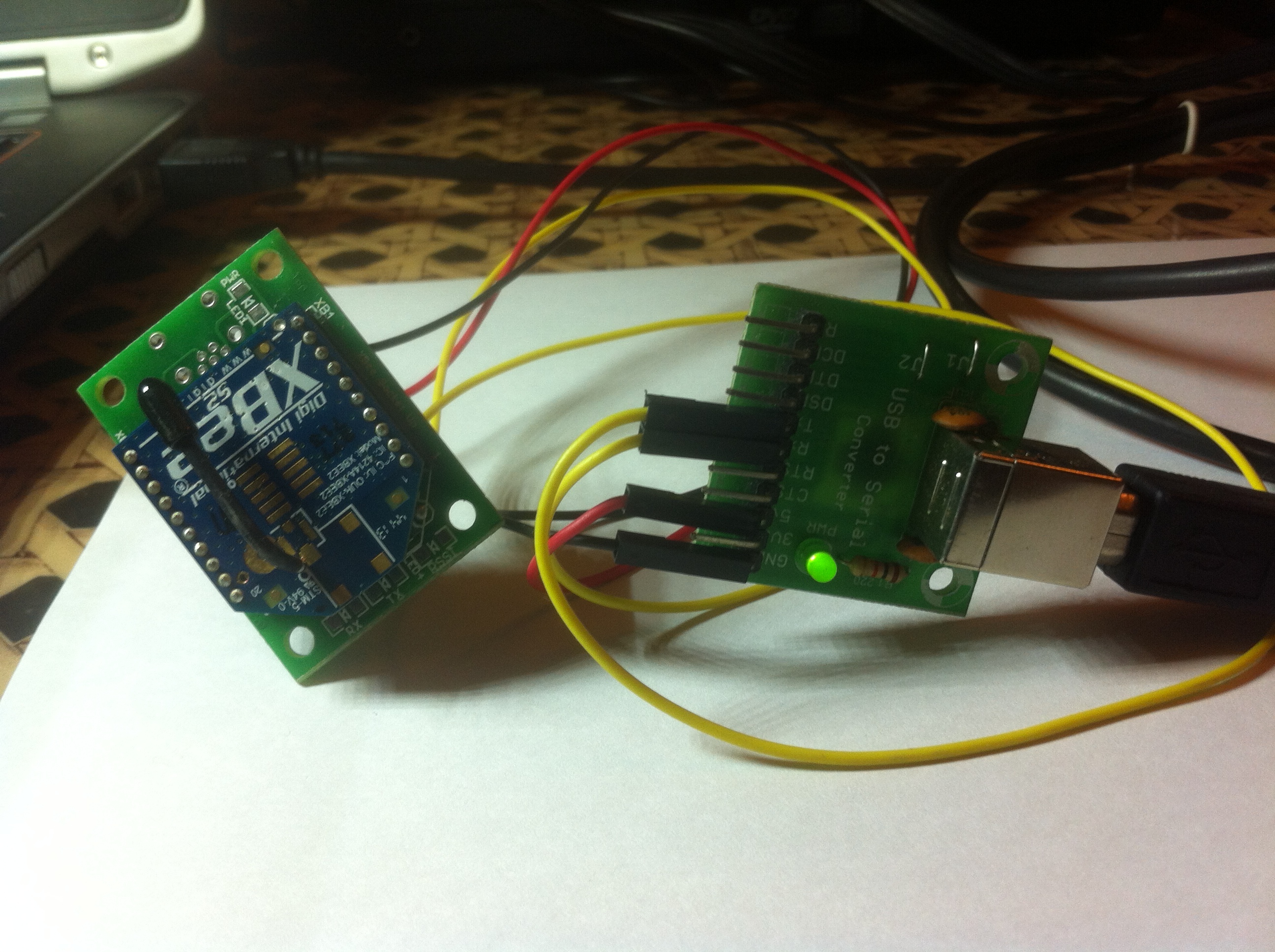
- One can use any other USB-TTL converter as well. In that case connect 5V and GND as mentioned above. BUT
- connect Tx pin of USB-TTL converter to Rx/Din (pin 3) of XBee
- connect Rx pin of USB-TTL converter to Tx/Dout (pin 2) of Xbee.
- Rest all pins of USB-TTL converter can be ignored.
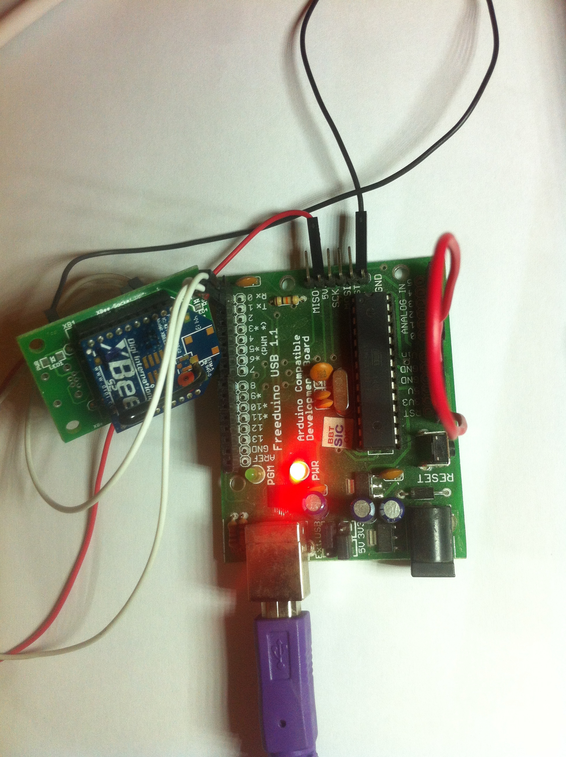
Arduino microcontroller board as USB-to-TTL converter
Standalone USB-TTL converter
Addressing
Every Xbee is assigned an 8 byte address. This address is printed on the backside of the Xbee.
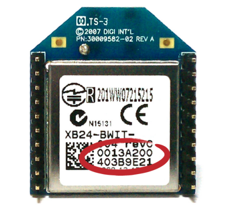
The addresses are represented as hex numbers. In hex every byte is represented by two hex numbers. That’s why we can see 8 hex numbers in first row (4 High bytes) and 8 hex numbers in second row (4 Low bytes). For API mode Coordinator needs to know Routers address. So we will note down address for one module only.
Let’s assume 1st Xbee as coordinator Xbee and 2nd Xbee as router Xbee.
In my case I have the following addresses:
1st Xbee high 4 bytes (Serial Number High / SH) = Coordinator module, address not needed
1st Xbee low 4 bytes (Serial Number Low / SL) = Coordinator module, address not needed
2nd Xbee high 4 bytes (Serial Number High / SH) = 00 13 A2 00
2nd Xbee low 4 bytes (Serial Number Low / SL) = 40 B8 F5 B7
Setting up Router XBee
Connect the Arduino microcontroller board based USB-to-TTL converter and 2nd Xbee setup at one USB port.
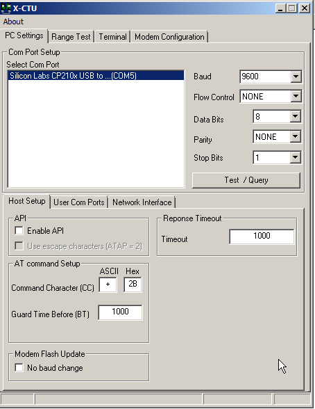
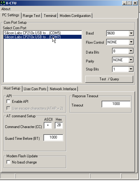
- Open the X-CTU and select the right COM port.
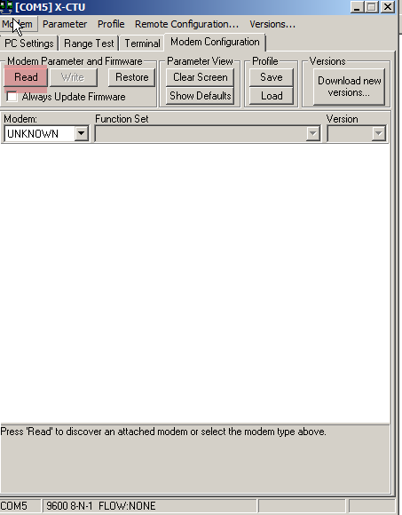
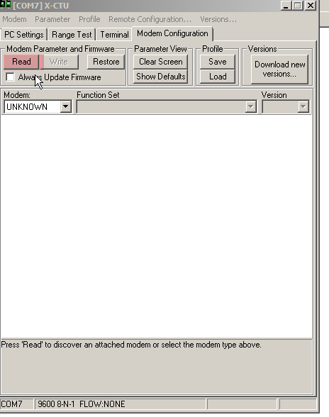
- Go to ‘Modem Configuration’ and click on read
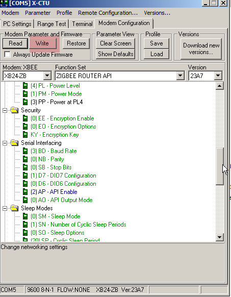
- Select ‘ZIGBEE ROUTER API’ in ‘Function Set’
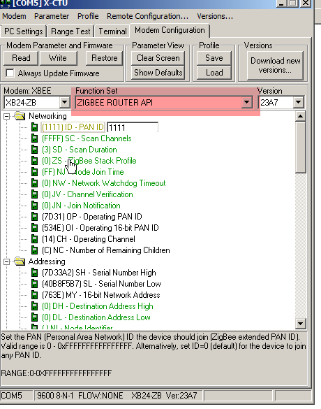
- Select a PAN ID. In my case I choose to set it to 1111.

- Set ‘API enable’ to 2
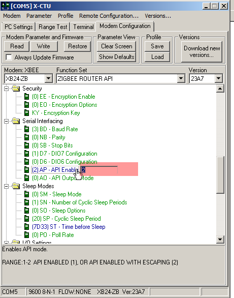
- Now hit ‘Write’ to write all these settings.
Setting Up Coordinator XBee
Connect the Arduino microcontroller board based USB-to-TTL converter and 1st Xbee setup at one USB port.
- Select the right COM port
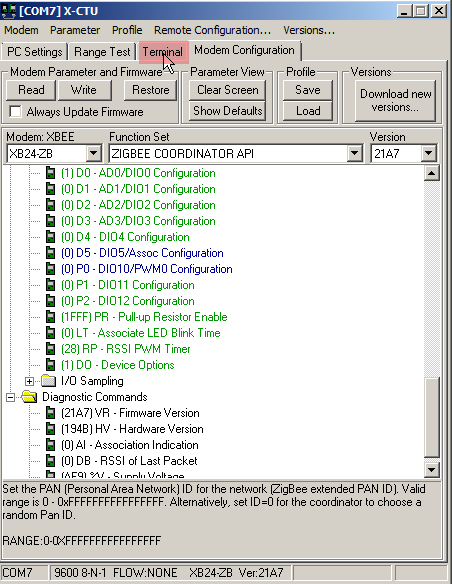
- Go to ‘Modem Configuration’ and click on ‘Read’
- Select ‘ZIGBEE COORDINATOR API’ from the ‘Function Set’
- Set the same ‘PAN ID’ that we set in the ‘Router’ module i.e 1111
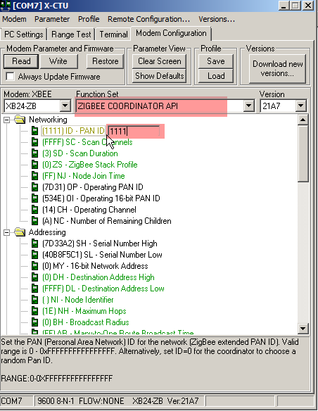
- Set ‘API Enable’ to 2
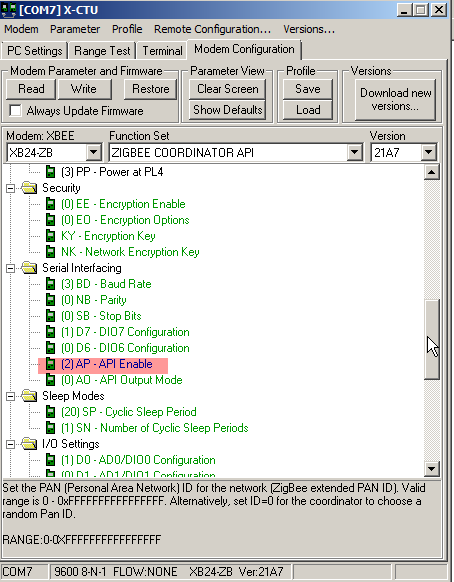
- Hit ‘Write’ to write these settings. Your 'Coordinatior Module; is ready.
Coordinator-Router communication
- Coordinator setup (Arduino microcontroller board based USB-to-TTL converter and 1st Xbee ) will remain same.
- Router setup
- Re-insert ATMEGA chip or remove the ‘RESET’ to ‘GND’ connection
- Connect a wire from 3.3 V socket to XBee’s pin 1
- Connect a wire from GND to XBee’s pin 10
- Connect the TX pin (pin 1) on arduino to XBee’s pin 3 (Rx/Din)
- Connect the Rx pin (pin 0) on arduino to XBee’s pin 2 (Tx/Dout)
Note that this time the Rx and Tx will be connected as twisted pair. Arduino Rx to Xbee Tx and Arduino Tx to Xbee Rx
-
Following is the code running at arduino. As you can see when I receive ‘ON’ text, few pins are set a HIGH. When I receive ‘OFF’ text, all those pins are set to LOW.
#include <XBee.h>
#include <SoftwareSerial.h>XBee xbee = XBee();
XBeeResponse response = XBeeResponse();
// create reusable response objects for responses we expect to handle
ZBRxResponse rx = ZBRxResponse();
ModemStatusResponse msr = ModemStatusResponse();int statusLed = 13;
int errorLed = 13;
int dataLed = 13;SoftwareSerial mySerial(10, 11); // RX, TX
//Relay for water pump
const int relay1Pin = 2;
//Relay for solenoid valve
const int relay2Pin = 3;void flashLed(int pin, int times, int wait) {
for (int i = 0; i < times; i++) {
digitalWrite(pin, HIGH);
delay(wait);
digitalWrite(pin, LOW);
if (i + 1 < times) {
delay(wait);
}
}
}void setup() {
pinMode(statusLed, OUTPUT);
pinMode(errorLed, OUTPUT);
pinMode(dataLed, OUTPUT);
pinMode(relay1Pin, OUTPUT);
pinMode(relay2Pin, OUTPUT);// start serial mySerial.begin(9600); xbee.begin(mySerial); flashLed(statusLed, 3, 50); Serial.begin(9600); digitalWrite(relay1Pin, LOW); digitalWrite(relay2Pin, LOW);}
// continuously reads packets, looking for ZB Receive or Modem Statusvoid loop() {
   xbee.readPacket();

   if (xbee.getResponse().isAvailable()) {
     // got something
     //Serial.println("here");
     if (xbee.getResponse().getApiId() == ZB_RX_RESPONSE) {
       // got a zb rx packet
       //Serial.println("here1");
       // now fill our zb rx class
       xbee.getResponse().getZBRxResponse(rx);

       if (rx.getOption() == ZB_PACKET_ACKNOWLEDGED) {
           // the sender got an ACK
           flashLed(statusLed, 10, 10);
       } else {
           // we got it (obviously) but sender didn't get an ACK
           flashLed(errorLed, 2, 20);
       }
       //Serial.println("here3");
       // set dataLed PWM to value of the first byte in the data
       //Serial.println("data" + rx.getData(0));
       char command[4];
       int i=0;
       for (; i < rx.getDataLength(); i++){
         command[i] = rx.getData(i);
       }
       command[i] =  '\0';
       Serial.println(command);
       if(String(command).equalsIgnoreCase("ON")){
         digitalWrite(dataLed, 1);
         digitalWrite(relay1Pin, HIGH);
         digitalWrite(relay2Pin, HIGH);
       }
       else if (String(command).equalsIgnoreCase("OFF")){
         digitalWrite(dataLed, 0);
         digitalWrite(relay1Pin, LOW);
         digitalWrite(relay2Pin, LOW);
       }

     } else if (xbee.getResponse().getApiId() == MODEM_STATUS_RESPONSE) {
       xbee.getResponse().getModemStatusResponse(msr);
       // the local XBee sends this response on certain events, like association/dissociation

       if (msr.getStatus() == ASSOCIATED) {
         // yay this is great.  flash led
         flashLed(statusLed, 10, 10);
       } else if (msr.getStatus() == DISASSOCIATED) {
         // this is awful.. flash led to show our discontent
         flashLed(errorLed, 10, 10);
       } else {
         // another status
         flashLed(statusLed, 5, 10);
       }
     } else {
       // not something we were expecting
       flashLed(errorLed, 1, 25);
     }
   } else if (xbee.getResponse().isError()) {
     //nss.print("Error reading packet.  Error code: ");
     //nss.println(xbee.getResponse().getErrorCode());
   }
}
Sending ‘ON’ text
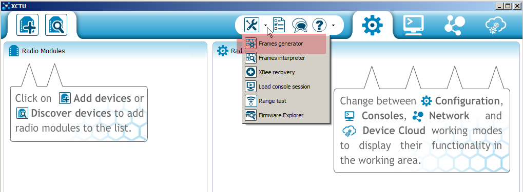
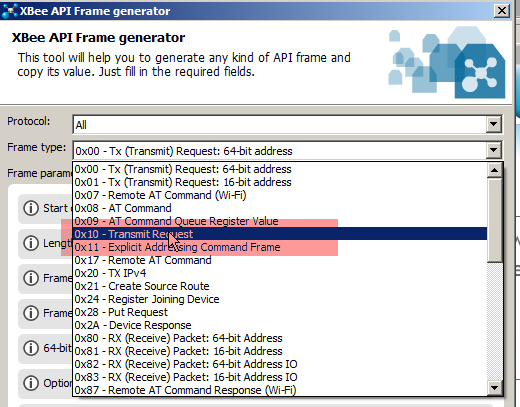
- open up the latest version of X-CTU and select the ‘Frames Generator’ option
- Select ‘All’ option from the Protocol drop down
- Select ‘0x10 - Transmit Request’ as ‘Frame Type’
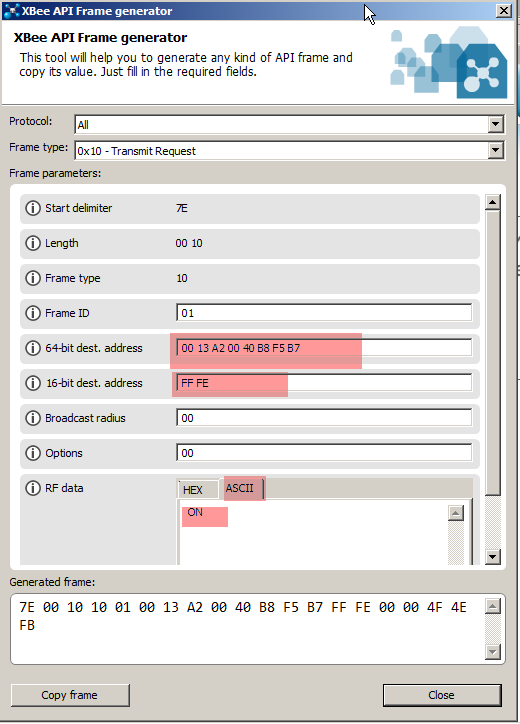
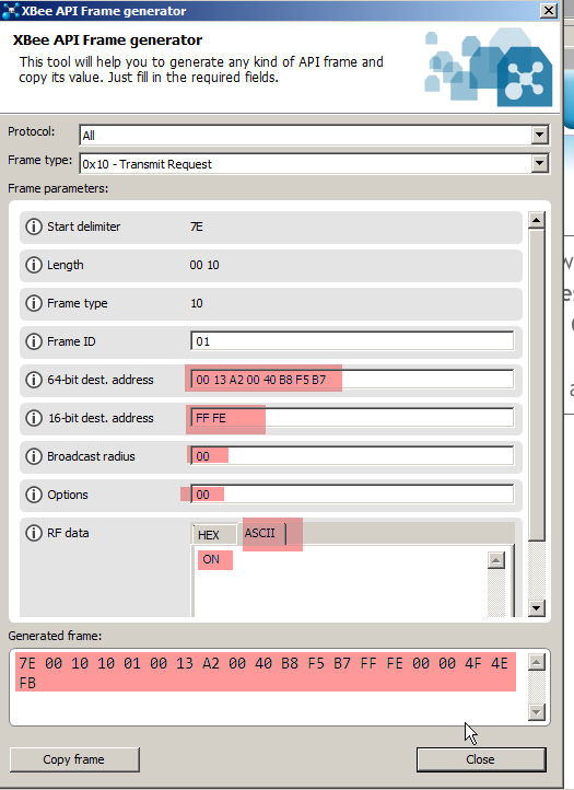
- Enter the 64 bit address of router module. For us it was ‘00 13 A2 00 40 B8 F5 B7’
- Enter the 16 bit address as ‘FF FE’
-
Set ‘Broadcast radius’ as 0
-
Set ‘Options’ as 0
-
Set ‘RF Data’ - ‘ASCII’ value as ON
-
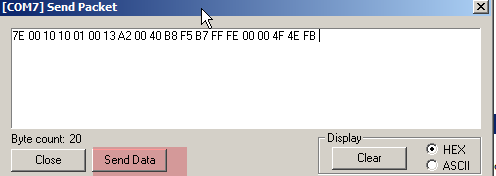
It will generate the frame as following
-
Go back to old X-CTU of coordinator module
-
Click on the ‘Terminal’ tab on the X-CTU of coordinator module
-
Click ‘Assemble Packet’
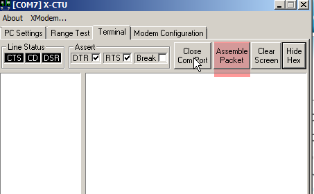
-
It will open a packet assembler window, select ‘HEX’ in it
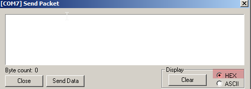
-
Copy the generate frame and paste it in ‘Send Packet’ window
-
Hit ‘Send Data’
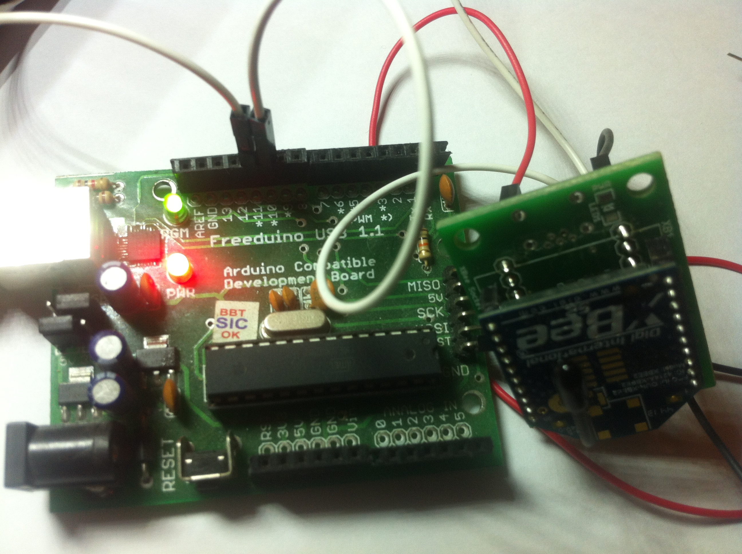
-
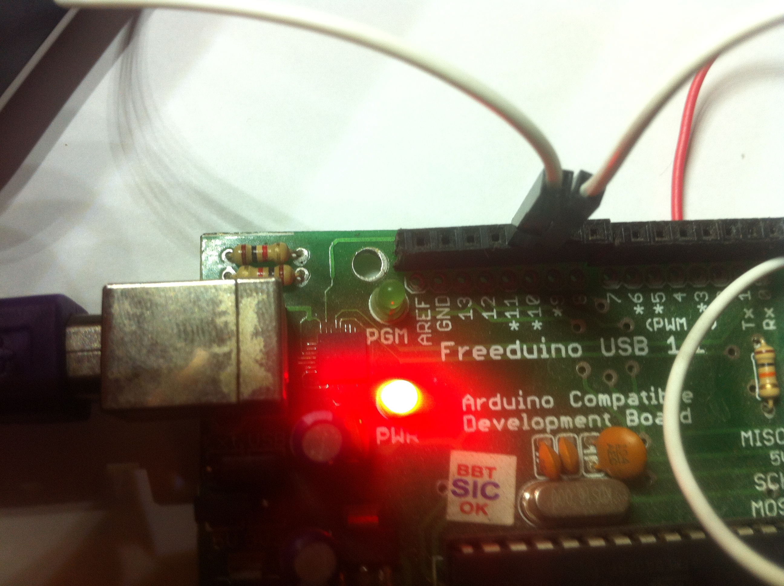
We can see the led number 13 (Green LED near PGM) is ON


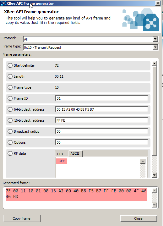
Sending ‘OFF’ text
- open up the latest version of X-CTU and select the ‘Frames Generator’ option
- Select ‘All’ option from the Protocol drop down
- Select ‘0x10 - Transmit Request’ as ‘Frame Type’
- Enter the 64 bit address of router module. For us it was ‘00 13 A2 00 40 B8 F5 B7’
- Enter the 16 bit address as ‘FF FE’
-
Set ‘Broadcast radius’ as 0
-
Set ‘Options’ as 0
-
Set ‘RF Data’ - ‘ASCII’ value as OFF
-
It will generate the frame as following
-
Hit ‘Send Data’
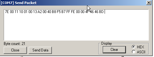
- We can see the led number 13 (Green LED near PGM) is OFF