To program the Xbee modules so that it can either act as router or coordinator, we will have to connect it to a PC. Xbee modules uses serial communication so we will need a USB-To-Serial-TTL converter. There are two ways to achieve this
- Standalone USB-To-Serial-TTL converter
- Arduino as USB-To-Serial-TTL converter
- FTDI cable
Standalone USB-To-Serial-TTL converter
One can purchase one from probots
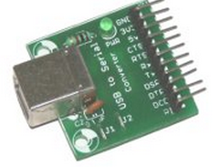
As you can see it has usb port at one end. This needs to be connected to your PCs USB port.Then do the following
Connections
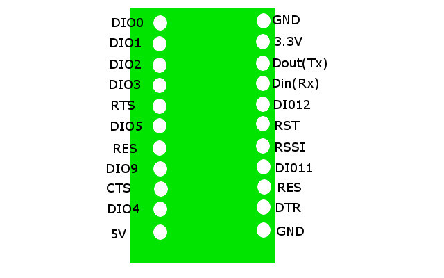
- GND of TTL converter to GND of Xbee module breakout board
- 5V of TTL converter to 5V of Xbee module breakout board
- RX of TTL converter to Dout(Tx) of Xbee module breakout board
- Tx of TTL converter to Din(Rx) of Xbee module breakout board
Arduino has a CP1202 chip that reads USB and converts that serial. Internally tx is then connected to tx and
Arduino as USB-To-Serial-TTL converter
A standard Arduino includes a USB to TTL chip so we can make it as a adapter.
Connect the RESET pin on the Arduino, to the GND pin on the Arduino. On some of the smaller Arduino’s, like Arduino Nano, the RESET pin is labeled RST. What this does is isolates the Atmega328p CPU from the IO-pins. Another solution is actually physically removing the Atmega328p processor from the socket, but because a lot of Arduino models doesn’t have that capability, the isolation way is the best practice.
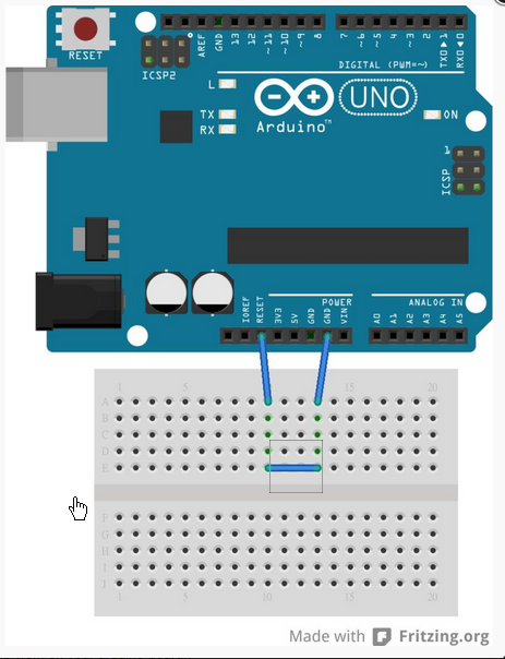
If we look at the schematic of Arduino, we will see that the RX and TX pins are connected to the FTDI chip (as we expected) and theese pins are pinned out at the Arduino board as pin 0 and pin 1 . That means we can use those pins for using the FTDI chip itself.
Connections
- GND of Arduino converter to GND of Xbee module breakout board
- 5V of Arduino converter to 5V of Xbee module breakout board
- RX of Arduino converter to Din(Rx) of Xbee module breakout board
- Tx of Arduino converter to Dout(Tx) of Xbee module breakout board
References
http://www.kobakant.at/DIY/?p=204
FTDI cable
FTDI cable will have USB port as one end and the following wires at other end -
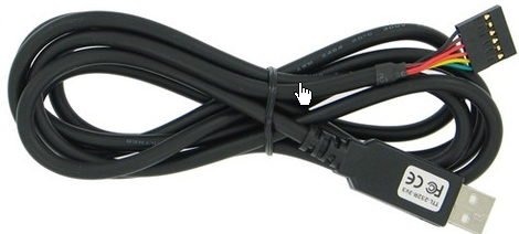
To program the firmware on an XBee the six pins of the FTDI cable should be connected as follows:
1 (Black) - ground
2 (Brown) - cts
3 (Red) - This is 5V VCC even on the 3.3V cable. If you want to power the module from this cable you will need to adapt this power level down to 3.3V. (VCC will go to pin 1 but be careful to have the correct voltage.)
4 (Orange) - tx
5 (Yellow) - rx
6 (Green) - rts
Connections
- GND of FTDI cable to GND of Xbee module breakout board
- 5V of FTDI cable to 5V of Xbee module breakout board
- RX of FTDI cable to Dout(Tx) of Xbee module breakout board
- Tx of FTDI cable to Din(Rx) of Xbee module breakout board
References
For more details on serial communication, please refer to -
https://learn.sparkfun.com/tutorials/serial-communication