Breakout board
Xbee modules pin spacing is not breadboard friendly and they work at 3.3 V. That means you can’t wire the arduino high to xbee board directly as arduino high is +5V and xbee works only with +3.3 V.
We need some sort of adapter, that can enhance the pin spacing of xbee to make it breadboard friendly. This adapter will also ensure to translate the 5V serial signals to 3.3V so that you can connect a 5V (down to 3.3V) system to any XBee module
In India one can buy these breakout boards from Visha Electronics. These cost around 250 per piece
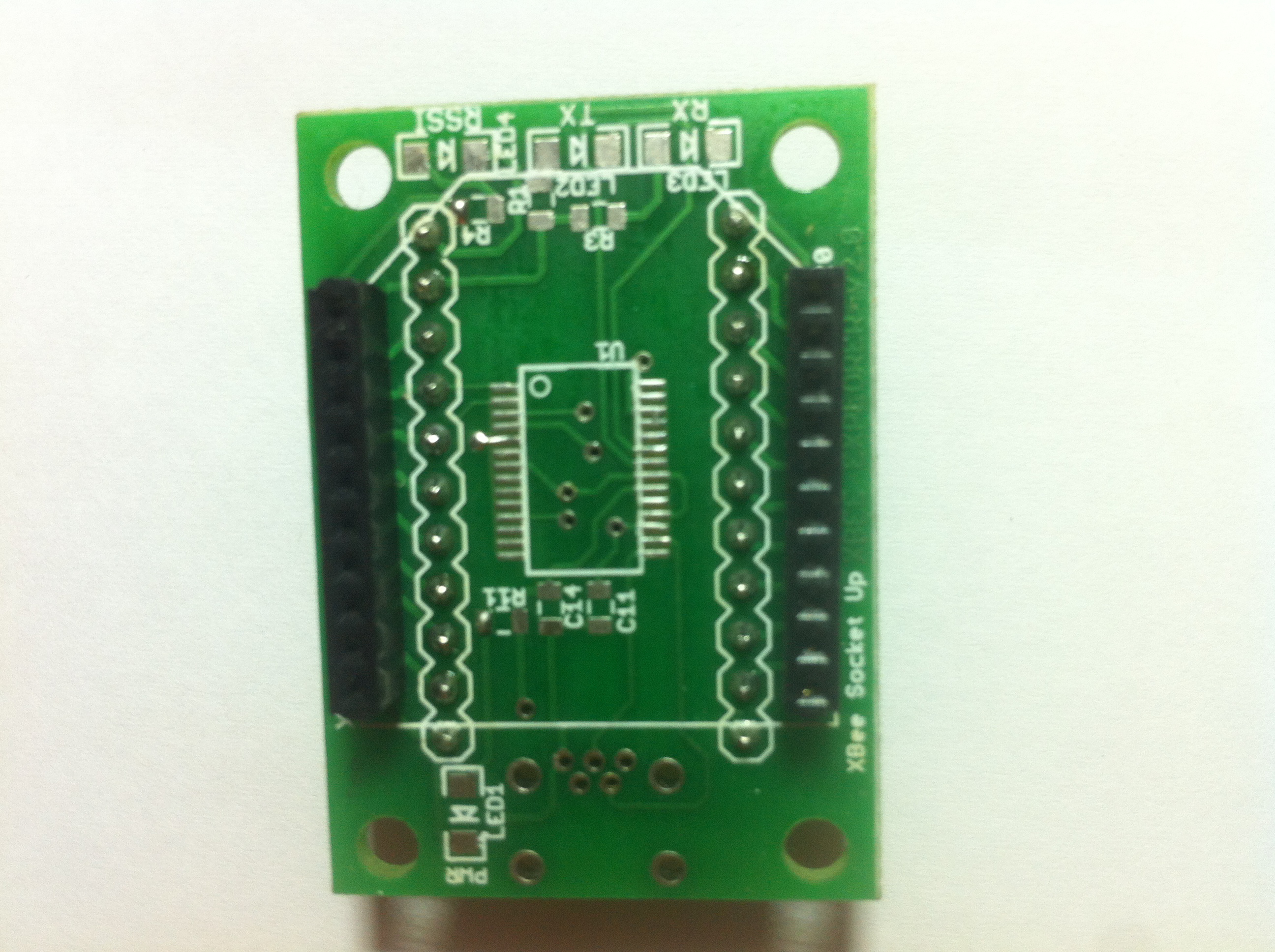
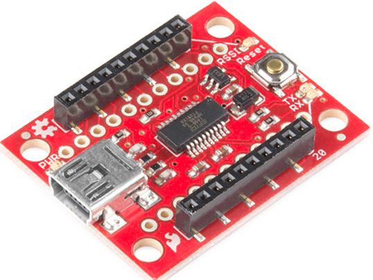
Front side
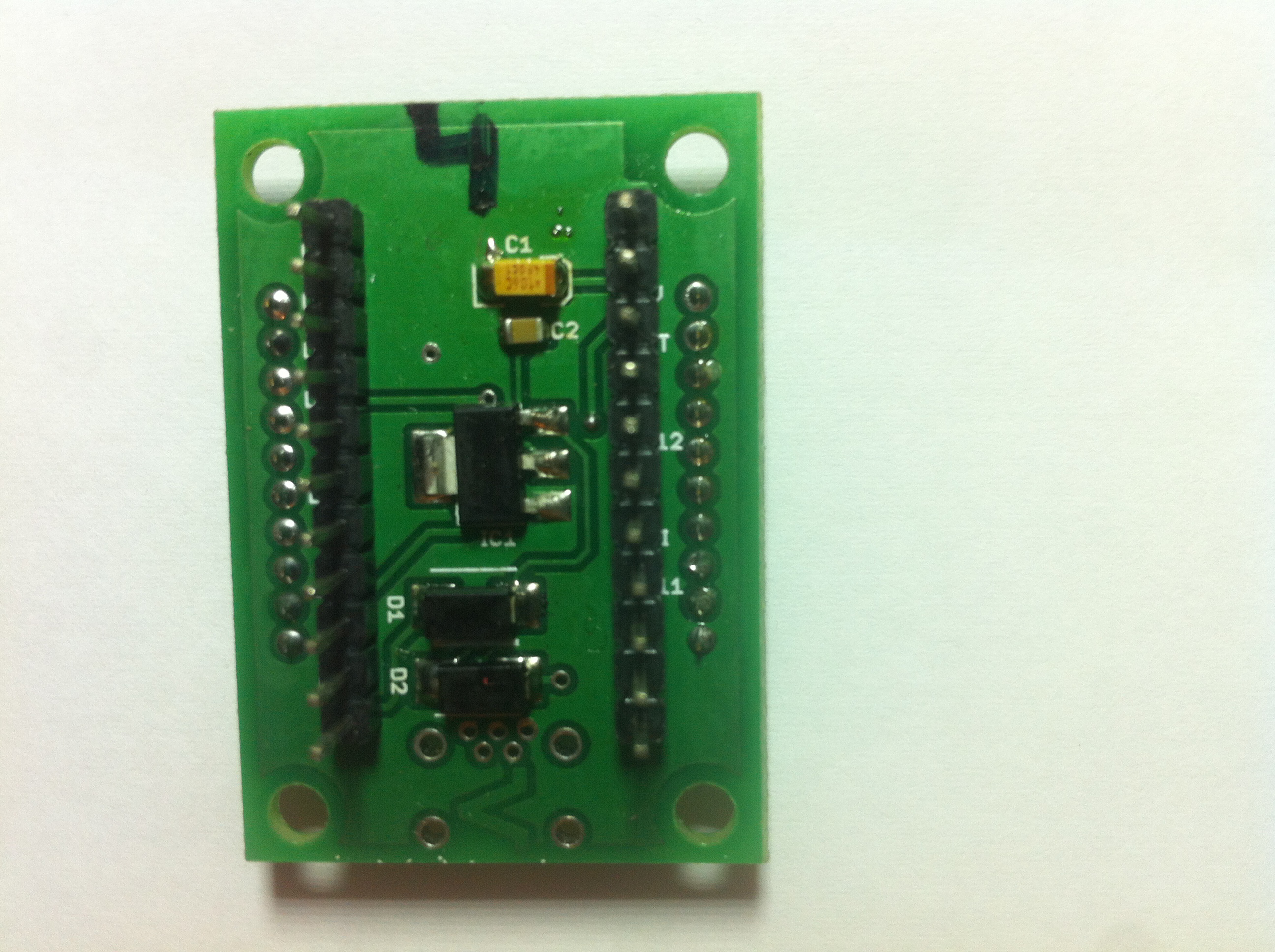
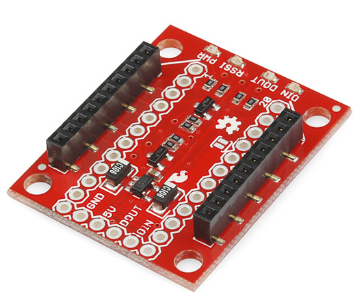
Back side
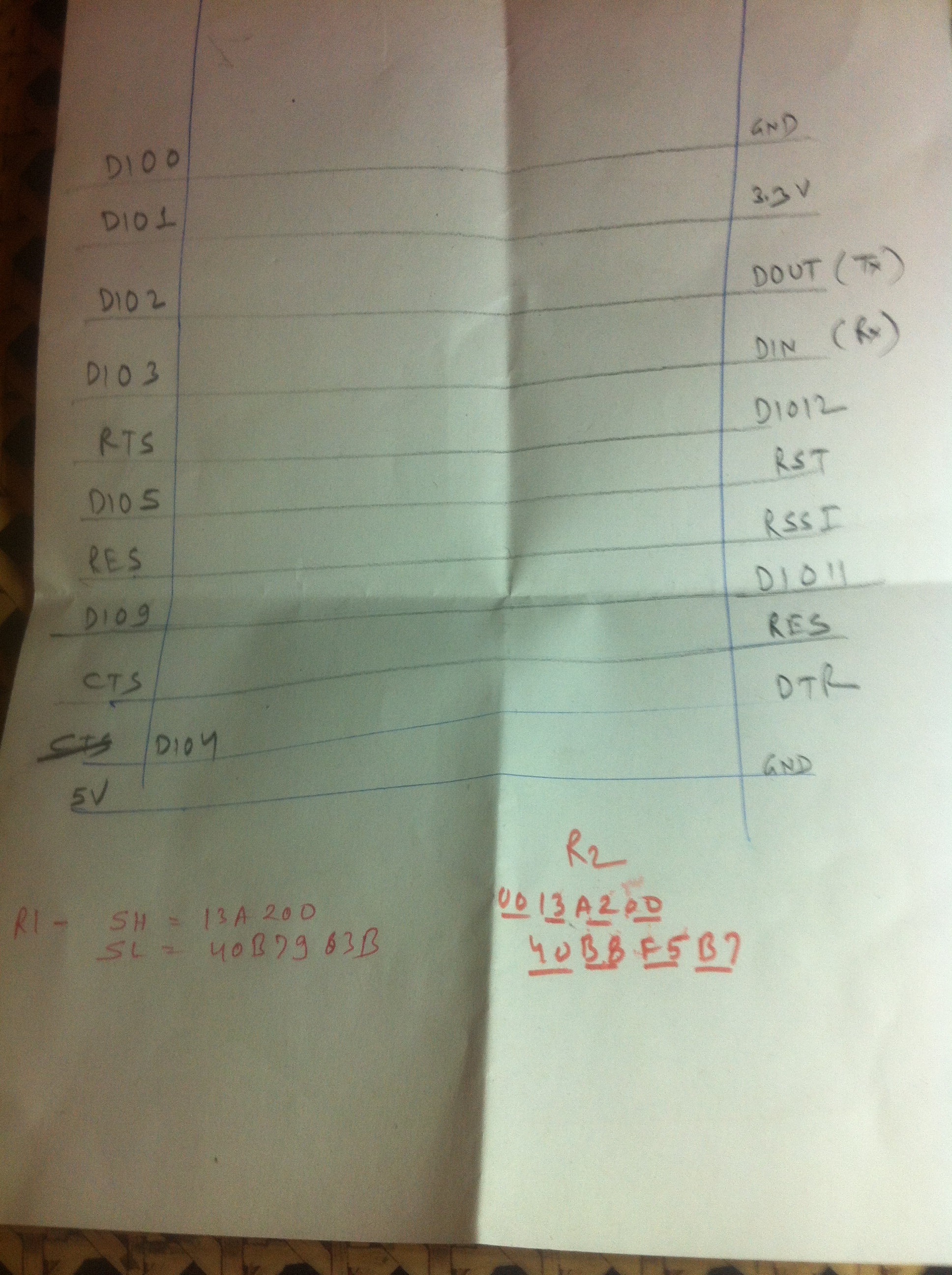
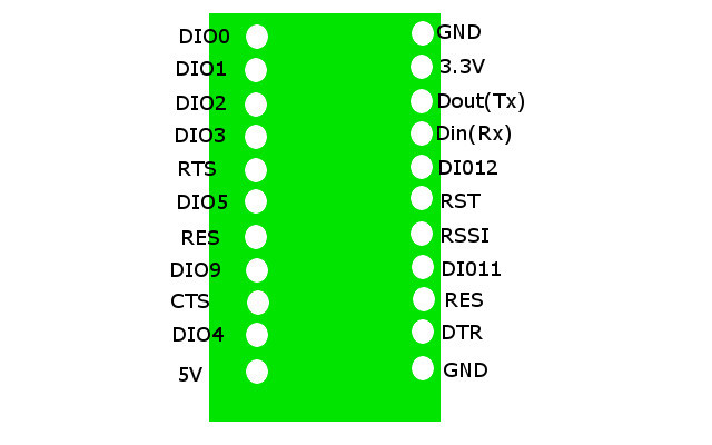
Pin layout for backside
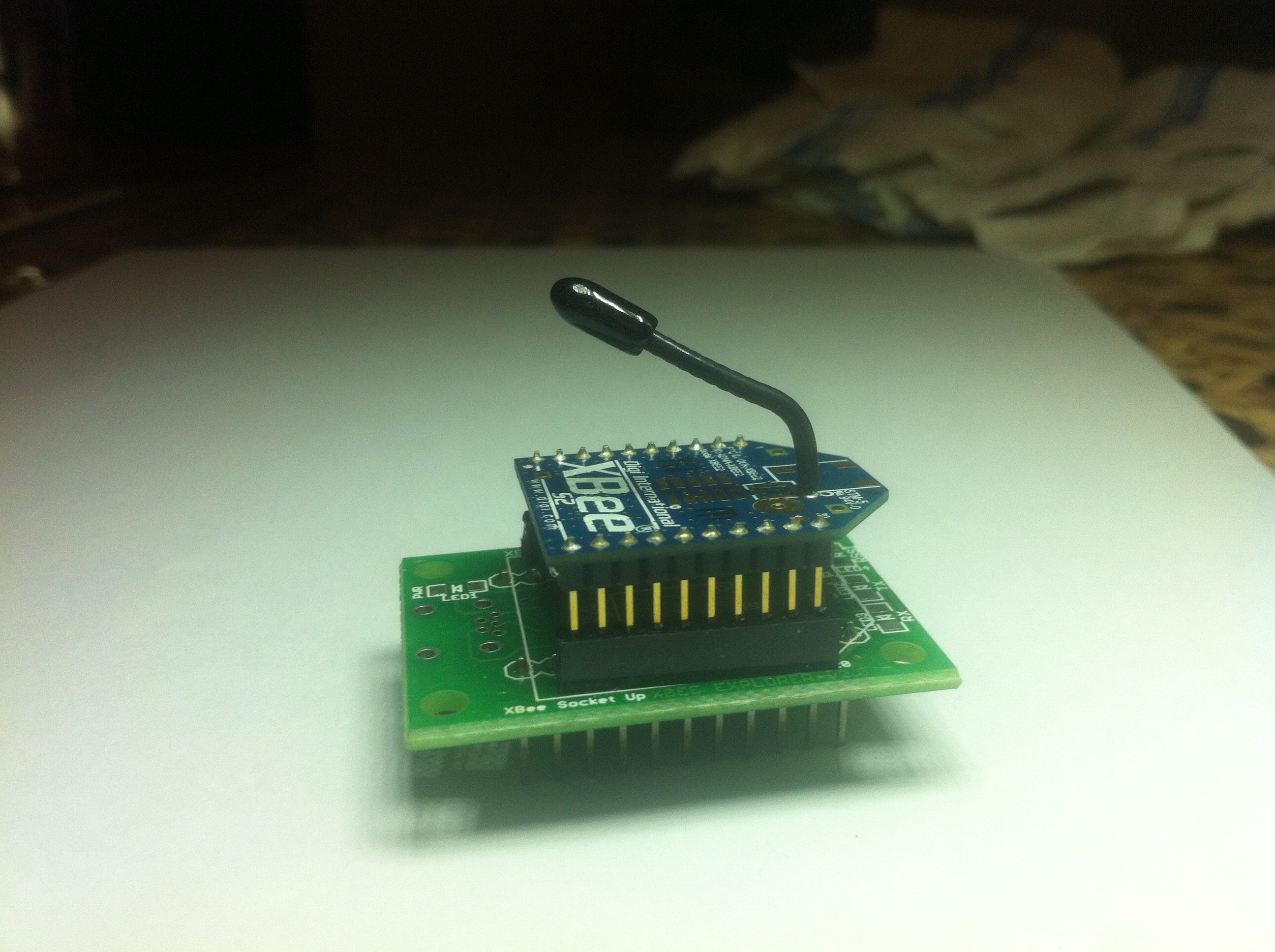
Xbee module connected
In my case, all the breakout boards that I have got have the caps covering the pin labels. So it was impossible for me to know what is Data-in, Data-out etc. I then used a screw driver to push the caps up so that I could read all the labels. I am posting the breakout sockets pin layouts in case someone is interested
For the reference, I am attaching a link from sparkfun
https://www.sparkfun.com/products/11373
USB Expolrer
To program these Xbee modules, we will have to connect these Xbee modules to the PC. To connect these modules to the PC, one option is to purchase a USB explorer. One such explorer is listed below for the reference
https://www.sparkfun.com/products/11812
But these explorers are not needed if you have a breakout board and any usb-to-serial-TTL converter. In the next article I will explain how to use usb-to-serial-TTL converter along with a breakout board to connect xbee module to PC.