In the previous article ( Xbee - Part 7 - Led on/off using API mode - linux - Freemindscafe ), I had used arduino microcontroller to drive a relay. I had a coordinator-router setup. Coordinator was sending on/off signal to router and in turn arduino connected to router was sending on/off signal to relay. My setup was as follows -
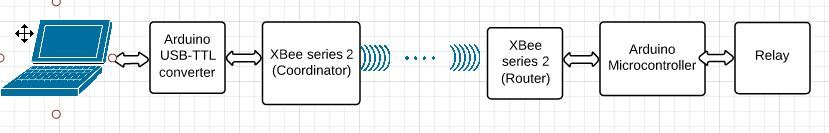
- Coordinator module was connected to the PC using Arduino micro-controller board based USB-to-TTL converter. Here arduino microcontroller was being used as USB-to-TTL converter only, there was no other purpose.
- Router module was connected to arduino microcontroller. Here micro controller was being used to signal relay on and off.
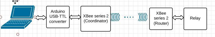
In this article, we will see how can we get rid off micro-controller at the router end. Since the only purpose of this micro-controller was to provide a high/low signal to relay. We can instead use Xbee series 2 module itself to provide low/high signal.
We want to achieve the following setup.
Since the XBee modules work only at 3.3 V level, I am assuming that XBee module is connected to some breakout board so that input 5V signals can be converted to 3.3 V. The relay that I am using can work with 3.3 V so it can be driven from XBee module directly; please do check for voltage compatibility the equipment that you are trying to signal from XBee
The complete setup remains the same as mentioned over here Xbee - Part 7 - Led on/off using API mode - linux - Freemindscafe . Just remove the arduino micro-controller from the router end and directly connect power supply to XBee and XBee to Relay.
AT commands
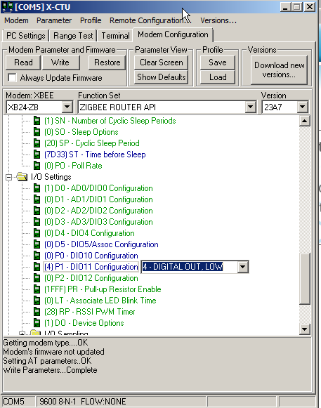
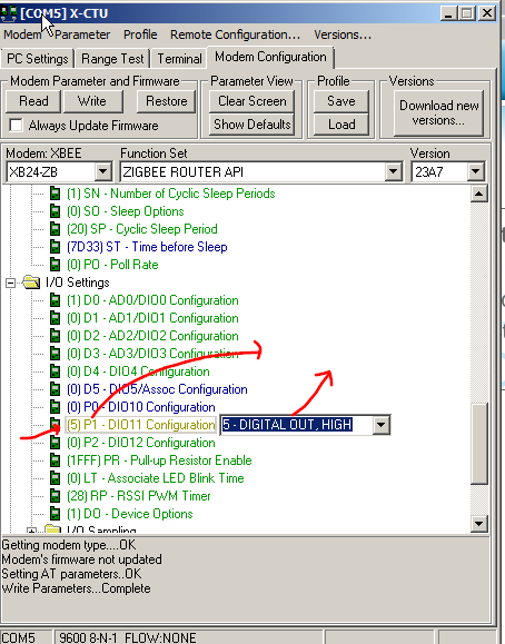
- Using AT commands at the router module one can drive XBee series 2 output pin high or low. Here we will use the DIO11 (XBee pin number 7) .
To drive a pin output low
To drive a pin output high
-
We need to send this AT command remotely from Coordinator XBee module to Router XBee module.
-
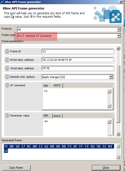
Using frame generator, generate the following frame. 64-bit destination address is address of the router module. AT command is ASCII ‘P1’ as it corresponds to DIO11 of I/O Setting ( see above ). Parameter value will be HEX 04 to drive the pin low and 05 to drive the pin high.
- Send this frame from Router module.